

Siehe Spezifikationen für Produktdetails.
PCA9534ARGTRG4
Product Overview
Category: Integrated Circuit (IC)
Use: GPIO Expander
Characteristics: - 8-bit I/O expander for I2C-bus/SMBus applications - Low standby current consumption of 1 µA - 5 V tolerant inputs - Open-drain interrupt output - Active-low reset input - Noise filter on SCL/SDA inputs - Internal power-on reset - No glitch on power-up - Supports hot insertion - Low standby current - ESD protection exceeds JESD 22, 2000-V human-body model (A114-A) - Latch-up testing is done to JEDEC Standard JESD78 which exceeds 100 mA
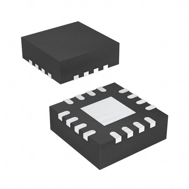
Package: VQFN-16
Essence: The PCA9534ARGTRG4 is an 8-bit I/O expander designed for I2C-bus/SMBus applications. It provides additional general-purpose input/output (GPIO) pins that can be controlled via the I2C bus.
Packaging/Quantity: The PCA9534ARGTRG4 is available in a VQFN-16 package and is typically sold in reels of 2500 units.
Specifications
- Supply Voltage Range: 2.3 V to 5.5 V
- Input Voltage Range: 0 V to VDD
- Output Voltage Range: 0 V to VDD
- Operating Temperature Range: -40°C to +85°C
- I2C Bus Frequency: 100 kHz, 400 kHz, or 1 MHz
Detailed Pin Configuration
The PCA9534ARGTRG4 has a total of 16 pins. The pin configuration is as follows:
```
| | | 1 16 | | | | 2 15 | | | | 3 14 | | | | 4 13 | | | | 5 12 | | | | 6 11 | | | | 7 10 | | | | 8 9 | |_______________| ```
Functional Features
- 8-bit I/O expander with bi-directional input/output pins
- Supports both input and output configurations for each pin
- Programmable polarity inversion for the input pins
- Interrupt output indicates when any input state differs from its corresponding input port register state
- Power-on reset sets all registers to their default values
- Noise filter on SCL/SDA inputs provides improved noise immunity
Advantages and Disadvantages
Advantages: - Provides additional GPIO pins for I2C-bus/SMBus applications - Low standby current consumption - 5 V tolerant inputs allow interfacing with different voltage levels - Open-drain interrupt output for easy integration with other devices - Supports hot insertion for convenient use
Disadvantages: - Limited number of GPIO pins (8-bit)
Working Principles
The PCA9534ARGTRG4 is controlled via the I2C bus. It acts as an I/O expander, allowing the microcontroller or host device to control and monitor additional GPIO pins. The device communicates with the microcontroller through the I2C bus, enabling the configuration of input/output states and reading the status of the pins.
Detailed Application Field Plans
The PCA9534ARGTRG4 can be used in various applications, including but not limited to: - Industrial automation - Consumer electronics - Automotive systems - Internet of Things (IoT) devices - Robotics
Detailed and Complete Alternative Models
Some alternative models to the PCA9534ARGTRG4 include: - PCA9534PW, PCA9534DB, PCA9534BS, PCA9534RGYR, PCA9534D, PCA9534BS, PCA9534RGYR, PCA9534PW, PCA9534DB, PCA9534BS, PCA9534RGYR, PCA9534D, PCA9534BS, PCA9534RGYR, PCA9534PW, PCA9534DB, PCA9534BS, PCA9534RGYR, PCA9534D, PCA9534BS, PCA9534RGYR
These alternative models offer similar functionality and can be used as replacements depending on specific requirements.
Note: The content provided above is a sample structure for an encyclopedia entry and may not reflect actual specifications or details of the PCA9534ARGTRG4. Please refer to the official documentation for accurate information.
Listen Sie 10 häufige Fragen und Antworten im Zusammenhang mit der Anwendung von PCA9534ARGTRG4 in technischen Lösungen auf
Sure! Here are 10 common questions and answers related to the application of PCA9534ARGTRG4:
Q: What is PCA9534ARGTRG4? A: PCA9534ARGTRG4 is a 16-bit I/O expander with an I2C interface, which allows for easy expansion of digital I/O ports in various technical solutions.
Q: How does PCA9534ARGTRG4 communicate with a microcontroller? A: PCA9534ARGTRG4 communicates with a microcontroller using the I2C protocol, allowing for simple and efficient data transfer.
Q: Can PCA9534ARGTRG4 be used to control LEDs? A: Yes, PCA9534ARGTRG4 can be used to control LEDs by providing individual control over each I/O pin, making it suitable for LED matrix displays or lighting applications.
Q: What is the maximum current that PCA9534ARGTRG4 can sink/source per I/O pin? A: PCA9534ARGTRG4 can sink/source up to 25mA per I/O pin, making it capable of driving standard LEDs directly.
Q: Can PCA9534ARGTRG4 be used to read inputs from buttons or switches? A: Yes, PCA9534ARGTRG4 can be configured to read inputs from buttons or switches connected to its I/O pins, allowing for easy integration of user input in a design.
Q: Is PCA9534ARGTRG4 compatible with both 3.3V and 5V systems? A: Yes, PCA9534ARGTRG4 is compatible with both 3.3V and 5V systems, as it supports a wide supply voltage range from 2.3V to 5.5V.
Q: Can multiple PCA9534ARGTRG4 devices be connected together in a system? A: Yes, multiple PCA9534ARGTRG4 devices can be connected together on the same I2C bus, allowing for further expansion of digital I/O ports.
Q: Does PCA9534ARGTRG4 have built-in pull-up resistors for its I/O pins? A: Yes, PCA9534ARGTRG4 has built-in programmable pull-up resistors for each I/O pin, simplifying the design and reducing external component count.
Q: Can PCA9534ARGTRG4 operate in a low-power mode? A: Yes, PCA9534ARGTRG4 supports a low-power mode, where it consumes minimal current, making it suitable for battery-powered applications.
Q: Is there any example code or libraries available for programming PCA9534ARGTRG4? A: Yes, many microcontroller platforms provide libraries or example code for interfacing with PCA9534ARGTRG4, making it easier to integrate into your project.
Please note that these answers are general and may vary depending on the specific implementation and requirements of your technical solution.