

Siehe Spezifikationen für Produktdetails.
CD74ACT164E
Product Overview
- Category: Integrated Circuit
- Use: Shift Register
- Characteristics: High-Speed, CMOS Logic, 8-Bit Serial-In/Parallel-Out
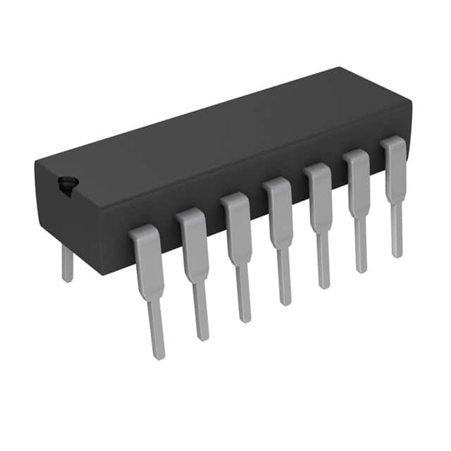
- Package: 14-Pin DIP (Dual In-Line Package)
- Essence: The CD74ACT164E is a high-speed CMOS logic integrated circuit that functions as an 8-bit serial-in/parallel-out shift register.
- Packaging/Quantity: Available in tubes or reels, with quantities varying based on customer requirements.
Specifications
- Logic Family: ACT
- Number of Bits: 8
- Serial Input: Yes
- Parallel Output: Yes
- Operating Voltage Range: 4.5V to 5.5V
- Operating Temperature Range: -40°C to +85°C
- Propagation Delay: 6 ns (typical)
- Output Drive Capability: ±24 mA
- Power Dissipation: 500 mW (max)
Pin Configuration
The CD74ACT164E has a total of 14 pins, which are assigned specific functions:
- SER (Serial Data Input)
- CLK (Clock Input)
- GND (Ground)
- QA (Parallel Output A)
- QB (Parallel Output B)
- QC (Parallel Output C)
- QD (Parallel Output D)
- QE (Parallel Output E)
- QF (Parallel Output F)
- QG (Parallel Output G)
- QH (Parallel Output H)
- VCC (Positive Power Supply)
- MR (Master Reset)
- QH' (Complementary Parallel Output H)
Functional Features
- High-speed operation allows for efficient data transfer.
- CMOS logic ensures low power consumption and compatibility with a wide range of devices.
- Serial-in/parallel-out functionality enables easy conversion between serial and parallel data formats.
- Master reset (MR) input allows for clearing the shift register to a known state.
Advantages
- Fast data transfer speeds due to high-speed CMOS technology.
- Low power consumption, making it suitable for battery-powered applications.
- Versatile functionality allows for various data manipulation tasks.
- Compact package size enables integration into space-constrained designs.
Disadvantages
- Limited number of bits (8) may not be sufficient for certain applications requiring larger data storage.
- Sensitivity to voltage fluctuations may require additional voltage regulation circuitry in some cases.
Working Principles
The CD74ACT164E operates based on the principle of shifting data through its internal registers. The serial data input (SER) is clocked into the shift register on each rising edge of the clock input (CLK). The shifted data is then available at the parallel output pins (QA-QH). The master reset (MR) input can be used to clear the shift register to a known state.
Application Field Plans
The CD74ACT164E can be utilized in various applications, including but not limited to:
- Data communication systems
- Digital displays
- Serial-to-parallel data conversion
- Data storage and retrieval systems
- Industrial automation control systems
Alternative Models
There are several alternative models available that offer similar functionality to the CD74ACT164E. Some notable alternatives include:
- SN74HC164N by Texas Instruments
- 74HC164 by NXP Semiconductors
- CD4015BE by Texas Instruments
- 74LS164 by Fairchild Semiconductor
These alternatives may have slight variations in specifications and pin configurations, so it is important to refer to their respective datasheets for detailed information.
Word count: 345
Listen Sie 10 häufige Fragen und Antworten im Zusammenhang mit der Anwendung von CD74ACT164E in technischen Lösungen auf
Sure! Here are 10 common questions and answers related to the application of CD74ACT164E in technical solutions:
Q: What is CD74ACT164E? A: CD74ACT164E is a 8-bit serial-in/parallel-out shift register integrated circuit (IC) commonly used in digital electronics.
Q: What is the purpose of CD74ACT164E? A: CD74ACT164E is used to convert serial data into parallel data, making it useful for applications such as data storage, data transfer, and control signal generation.
Q: What is the maximum clock frequency supported by CD74ACT164E? A: CD74ACT164E can operate at a maximum clock frequency of 100 MHz.
Q: How many input pins does CD74ACT164E have? A: CD74ACT164E has a single serial input pin and eight parallel output pins.
Q: Can CD74ACT164E be cascaded to increase the number of bits? A: Yes, multiple CD74ACT164E ICs can be cascaded together to increase the number of bits in the shift register.
Q: What is the power supply voltage range for CD74ACT164E? A: CD74ACT164E operates with a power supply voltage range of 4.5V to 5.5V.
Q: Does CD74ACT164E support tri-state outputs? A: No, CD74ACT164E does not have tri-state outputs. The outputs are always active and drive either high or low logic levels.
Q: Can CD74ACT164E be used in both synchronous and asynchronous modes? A: Yes, CD74ACT164E can be used in both synchronous and asynchronous modes of operation.
Q: What is the typical propagation delay of CD74ACT164E? A: The typical propagation delay of CD74ACT164E is around 6 ns.
Q: Are there any special considerations for PCB layout when using CD74ACT164E? A: It is recommended to follow proper PCB layout guidelines, such as minimizing trace lengths, providing decoupling capacitors, and ensuring proper grounding, to optimize performance and minimize noise interference.
Please note that these answers are general and may vary depending on specific datasheet specifications and application requirements.