

Siehe Spezifikationen für Produktdetails.
Encyclopedia Entry: 74VHCT16373ATTR
Product Overview
- Category: Integrated Circuit (IC)
- Use: Digital Logic Device
- Characteristics: High-Speed, CMOS Technology
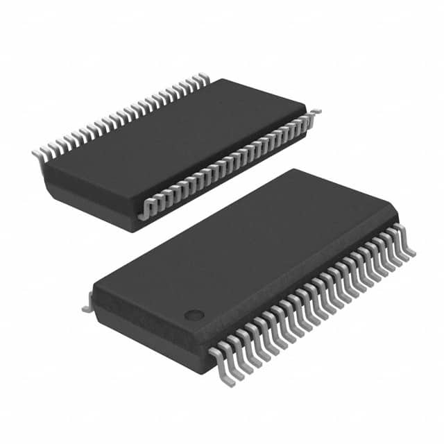
- Package: TSSOP (Thin Shrink Small Outline Package)
- Essence: 16-Bit Transparent D-Type Latch with 3-State Outputs
- Packaging/Quantity: Tape and Reel, 2500 units per reel
Specifications
- Supply Voltage Range: 2.0V to 5.5V
- Input Voltage Range: 0V to VCC
- Output Voltage Range: 0V to VCC
- Operating Temperature Range: -40°C to +85°C
- Output Drive Capability: ±24mA at 3.3V
- Propagation Delay Time: 4.5ns (typical)
Detailed Pin Configuration
The 74VHCT16373ATTR IC has a total of 48 pins, which are divided into four groups: 1. Group A (Pins 1-12): Data Inputs (D0-D11), Output Enable (OE), and Clock (CLK) inputs. 2. Group B (Pins 13-24): Data Inputs (D12-D23). 3. Group C (Pins 25-36): Data Inputs (D24-D35). 4. Group D (Pins 37-48): Data Inputs (D36-D47) and 3-State Outputs (Q0-Q15).
Functional Features
- 16-Bit Transparent D-Type Latch: The IC can store and latch 16 bits of data.
- 3-State Outputs: The outputs can be put in a high-impedance state, allowing multiple devices to share the same bus without interference.
- Output Enable (OE) Control: The OE input enables or disables the outputs.
- Clock (CLK) Input: The CLK input synchronizes the data transfer.
Advantages and Disadvantages
Advantages: - High-Speed Operation: The IC operates at a fast propagation delay time of 4.5ns, making it suitable for high-performance applications. - CMOS Technology: The use of CMOS technology provides low power consumption and wide voltage range compatibility. - 3-State Outputs: The ability to put the outputs in a high-impedance state allows for efficient bus sharing.
Disadvantages: - Limited Data Width: The IC can only store and latch 16 bits of data, which may not be sufficient for certain applications requiring larger data widths. - Package Size: The TSSOP package may be challenging to handle for some users due to its small size.
Working Principles
The 74VHCT16373ATTR is based on CMOS technology, which utilizes both NMOS and PMOS transistors to achieve low power consumption and high noise immunity. The IC functions as a transparent latch, allowing data to pass through when the latch enable signal (CLK) is active. The output enable signal (OE) controls the state of the outputs, enabling or disabling their functionality.
Detailed Application Field Plans
The 74VHCT16373ATTR IC finds applications in various digital systems, including but not limited to: 1. Microprocessors and Microcontrollers 2. Data Storage Systems 3. Communication Equipment 4. Industrial Control Systems 5. Automotive Electronics
Detailed Alternative Models
- 74HC16373: Similar to 74VHCT16373ATTR, but operates at a wider supply voltage range of 2.0V to 6.0V.
- 74ACT16373: Offers faster speed with a typical propagation delay time of 3.5ns, but requires a higher supply voltage range of 4.5V to 5.5V.
- 74LS16373: Operates at a lower speed with a typical propagation delay time of 10ns, but offers compatibility with TTL logic levels.
(Note: The alternative models listed above are just a few examples and not an exhaustive list.)
This encyclopedia entry provides an overview of the 74VHCT16373ATTR IC, including its product details, specifications, pin configuration, functional features, advantages, disadvantages, working principles, application field plans, and alternative models.
Listen Sie 10 häufige Fragen und Antworten im Zusammenhang mit der Anwendung von 74VHCT16373ATTR in technischen Lösungen auf
Sure! Here are 10 common questions and answers related to the application of 74VHCT16373ATTR in technical solutions:
Q: What is the 74VHCT16373ATTR? A: The 74VHCT16373ATTR is a 16-bit transparent latch with 3-state outputs, commonly used in digital circuits.
Q: What is the purpose of a transparent latch? A: A transparent latch allows data to pass through when its enable input is active, providing a way to store and transfer data in a circuit.
Q: How many bits can the 74VHCT16373ATTR handle? A: The 74VHCT16373ATTR can handle 16 bits of data.
Q: What does "3-state outputs" mean? A: 3-state outputs allow the outputs of the latch to be in one of three states: high, low, or high-impedance (disconnected).
Q: What voltage levels does the 74VHCT16373ATTR support? A: The 74VHCT16373ATTR supports both TTL (Transistor-Transistor Logic) and CMOS (Complementary Metal-Oxide-Semiconductor) voltage levels.
Q: Can I use the 74VHCT16373ATTR in both synchronous and asynchronous applications? A: Yes, the 74VHCT16373ATTR can be used in both synchronous and asynchronous applications.
Q: What is the maximum clock frequency supported by the 74VHCT16373ATTR? A: The maximum clock frequency supported by the 74VHCT16373ATTR depends on various factors such as supply voltage and temperature, but it typically ranges from a few megahertz to tens of megahertz.
Q: Can I cascade multiple 74VHCT16373ATTR latches together? A: Yes, you can cascade multiple 74VHCT16373ATTR latches together to increase the number of bits that can be stored or transferred.
Q: What is the power supply voltage range for the 74VHCT16373ATTR? A: The power supply voltage range for the 74VHCT16373ATTR is typically between 4.5V and 5.5V.
Q: Are there any specific precautions to consider when using the 74VHCT16373ATTR? A: It is important to ensure proper decoupling and bypass capacitors are used near the power supply pins to minimize noise and voltage fluctuations. Additionally, care should be taken to avoid exceeding the maximum ratings specified in the datasheet, such as voltage and current limits.
Please note that these answers are general and may vary depending on the specific application and requirements. Always refer to the datasheet and consult with a qualified engineer for accurate information.