

Siehe Spezifikationen für Produktdetails.
MC10E151FNR2
Product Overview
- Category: Integrated Circuit (IC)
- Use: Digital Logic Gate
- Characteristics: High-speed, ECL (Emitter-Coupled Logic) Technology
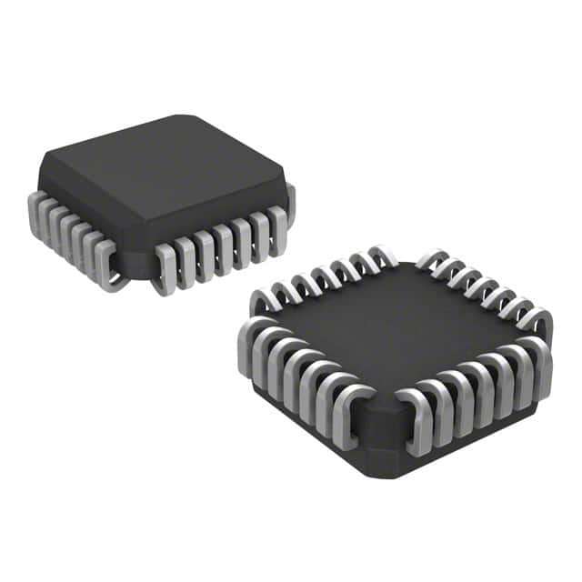
- Package: 28-pin PLCC (Plastic Leaded Chip Carrier)
- Essence: Logic gate with differential inputs and outputs
- Packaging/Quantity: Tape and Reel, 250 units per reel
Specifications
- Supply Voltage: -5.2V to -4.5V
- Operating Temperature: -40°C to +85°C
- Propagation Delay: 1.7 ns (typical)
- Input Voltage Levels: VEE-2.0V to VEE-0.8V
- Output Voltage Levels: VEE-2.0V to VEE-0.8V
- Input Current: ±20 mA (max)
- Output Current: ±100 mA (max)
Detailed Pin Configuration
The MC10E151FNR2 has a total of 28 pins. The pin configuration is as follows:
- VBB (Bias Supply Voltage)
- Q0 (Output 0)
- Q1 (Output 1)
- Q2 (Output 2)
- Q3 (Output 3)
- Q4 (Output 4)
- Q5 (Output 5)
- GND (Ground)
- D (Data Input)
- /D (Complementary Data Input)
- /Q5 (Complementary Output 5)
- /Q4 (Complementary Output 4)
- /Q3 (Complementary Output 3)
- /Q2 (Complementary Output 2)
- /Q1 (Complementary Output 1)
- /Q0 (Complementary Output 0)
- VCC (Positive Supply Voltage)
- Q6 (Output 6)
- Q7 (Output 7)
- Q8 (Output 8)
- Q9 (Output 9)
- Q10 (Output 10)
- Q11 (Output 11)
- GND (Ground)
- D (Data Input)
- /D (Complementary Data Input)
- /Q11 (Complementary Output 11)
- /Q10 (Complementary Output 10)
Functional Features
- Differential inputs and outputs for high-speed operation
- Compatible with other ECL logic families
- Wide operating temperature range
- Low power consumption
- High noise immunity
Advantages and Disadvantages
Advantages: - High-speed performance - Compatibility with other ECL logic families - Wide operating temperature range
Disadvantages: - Requires negative supply voltage - Limited availability of alternative models
Working Principles
The MC10E151FNR2 is a digital logic gate that operates based on the principles of Emitter-Coupled Logic (ECL). It uses differential inputs to provide high-speed signal processing capabilities. The gate performs logical operations on the input signals and produces corresponding output signals. The ECL technology ensures fast switching times and low propagation delays.
Detailed Application Field Plans
The MC10E151FNR2 can be used in various applications where high-speed digital signal processing is required. Some potential application fields include:
- Telecommunications: The IC can be used in high-speed data transmission systems, such as fiber optic networks and wireless communication systems.
- Computer Networking: It can be utilized in routers, switches, and network interface cards to handle high-speed data packets.
- Test and Measurement Equipment: The IC can be integrated into oscilloscopes, logic analyzers, and signal generators to process and analyze digital signals accurately.
- Industrial Automation: It can be employed in control systems, PLCs (Programmable Logic Controllers), and robotics for precise and fast data processing.
Detailed and Complete Alternative Models
While the MC10E151FNR2 is a reliable and widely used logic gate, there are alternative models available from different manufacturers. Some of the alternatives include:
- SN74ALS151: A TTL (Transistor-Transistor Logic) version of the logic gate offered by Texas Instruments.
- CD40151B: A CMOS (Complementary Metal-Oxide-Semiconductor) version of the logic gate provided by various manufacturers.
- 74HC151: A high-speed CMOS version of the logic gate manufactured by multiple companies.
These alternative models offer similar functionality but may have different specifications and pin configurations. Users should carefully review the datasheets of these alternatives to ensure compatibility with their specific requirements.
Word count: 547 words
Listen Sie 10 häufige Fragen und Antworten im Zusammenhang mit der Anwendung von MC10E151FNR2 in technischen Lösungen auf
Sure! Here are 10 common questions and answers related to the application of MC10E151FNR2 in technical solutions:
Q: What is MC10E151FNR2? A: MC10E151FNR2 is a specific type of integrated circuit (IC) that belongs to the MC10E series. It is designed for high-speed digital applications.
Q: What are the key features of MC10E151FNR2? A: MC10E151FNR2 features differential inputs, ECL outputs, and operates at high speeds up to 3.8 GHz.
Q: In what technical solutions can MC10E151FNR2 be used? A: MC10E151FNR2 can be used in various applications such as telecommunications, data communications, clock distribution, and high-speed signal processing.
Q: How does MC10E151FNR2 handle differential inputs? A: MC10E151FNR2 accepts differential inputs, which means it can process signals that have both positive and negative voltage levels.
Q: What is the power supply requirement for MC10E151FNR2? A: MC10E151FNR2 typically requires a power supply voltage of -5.2V and a ground reference voltage of 0V.
Q: Can MC10E151FNR2 operate at different temperature ranges? A: Yes, MC10E151FNR2 is designed to operate within a specified temperature range, typically from -40°C to +85°C.
Q: Does MC10E151FNR2 have any built-in protection features? A: MC10E151FNR2 does not have built-in protection features. External measures may need to be taken to protect the IC from voltage spikes or ESD events.
Q: What is the output format of MC10E151FNR2? A: MC10E151FNR2 provides emitter-coupled logic (ECL) outputs, which are commonly used in high-speed digital systems.
Q: Can MC10E151FNR2 be used in a multi-chip system? A: Yes, MC10E151FNR2 can be used in multi-chip systems where multiple ICs are interconnected to perform complex functions.
Q: Are there any application notes or reference designs available for MC10E151FNR2? A: Yes, the manufacturer of MC10E151FNR2 typically provides application notes and reference designs that can help users understand and implement the IC in their technical solutions.
Please note that the answers provided here are general and may vary depending on the specific requirements and use cases. It is always recommended to refer to the datasheet and documentation provided by the manufacturer for accurate information.