

Siehe Spezifikationen für Produktdetails.
Encyclopedia Entry: 74HCT273DB,118
Product Overview
Category
The 74HCT273DB,118 belongs to the category of integrated circuits (ICs).
Use
This IC is commonly used in digital electronics for storing and manipulating binary data. It serves as a D-type flip-flop with eight individual flip-flops within a single package.
Characteristics
- High-speed operation
- Low power consumption
- Compatibility with both TTL and CMOS logic levels
- Wide operating voltage range
- Compact package size
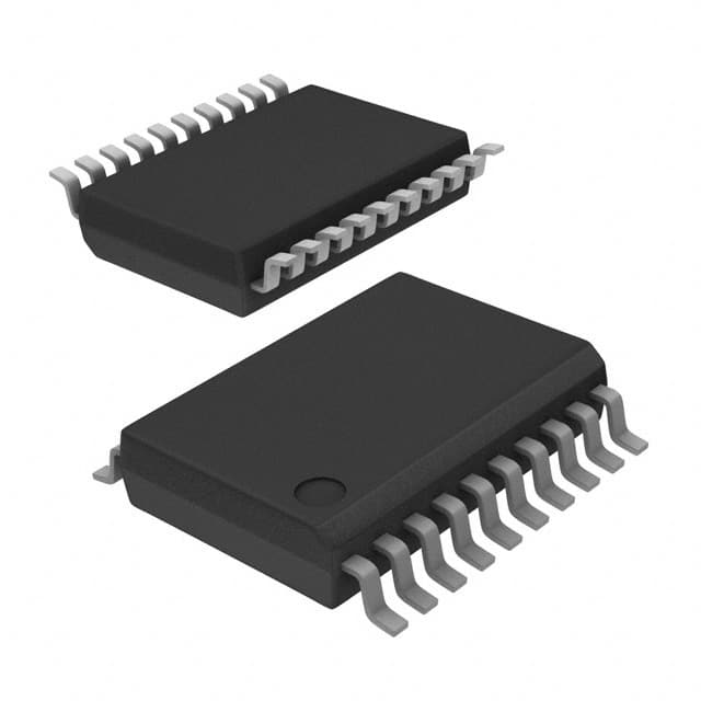
Package
The 74HCT273DB,118 is available in a standard 20-pin SSOP (Shrink Small Outline Package) format.
Essence
The essence of this product lies in its ability to store and retain digital information, making it an essential component in various electronic devices and systems.
Packaging/Quantity
The 74HCT273DB,118 is typically packaged in reels or tubes, with each reel containing a specific quantity of ICs. The exact quantity may vary depending on the manufacturer's specifications.
Specifications
- Supply Voltage Range: 2V to 6V
- Input Voltage Range: 0V to VCC
- Output Voltage Range: 0V to VCC
- Operating Temperature Range: -40°C to +125°C
- Maximum Clock Frequency: 25 MHz
- Propagation Delay Time: 15 ns (typical)
Detailed Pin Configuration
The 74HCT273DB,118 features a total of 20 pins, each serving a specific function. The pin configuration is as follows:
- Clear (CLR)
- Data (D0)
- Data (D1)
- Data (D2)
- Data (D3)
- Data (D4)
- Data (D5)
- Data (D6)
- Data (D7)
- Clock (CLK)
- Enable (EN)
- Output (Q0)
- Output (Q1)
- Output (Q2)
- Output (Q3)
- Output (Q4)
- Output (Q5)
- Output (Q6)
- Output (Q7)
- Ground (GND)
Functional Features
The 74HCT273DB,118 offers the following functional features:
- Eight individual D-type flip-flops
- Asynchronous clear input (CLR) for resetting all flip-flops
- Synchronous parallel loading of data inputs (D0-D7)
- Positive-edge triggered clock input (CLK)
- Enable input (EN) for controlling the operation of the flip-flops
- Buffered outputs (Q0-Q7) for accessing stored data
Advantages and Disadvantages
Advantages
- High-speed operation allows for efficient data storage and retrieval.
- Low power consumption makes it suitable for battery-powered devices.
- Compatibility with both TTL and CMOS logic levels ensures versatility in various circuit designs.
- Wide operating voltage range provides flexibility in different power supply configurations.
- Compact package size saves valuable board space.
Disadvantages
- Limited number of flip-flops (eight) may not be sufficient for certain applications requiring larger data storage capacity.
- Propagation delay time may introduce timing issues in high-frequency applications.
Working Principles
The 74HCT273DB,118 operates based on the principles of sequential logic. It utilizes D-type flip-flops to store and retain binary data. The clock input triggers the transfer of data from the input pins (D0-D7) to the corresponding output pins (Q0-Q7). The enable input controls the operation of the flip-flops, allowing for synchronous or asynchronous loading of data. The clear input resets all flip-flops to a known state.
Detailed Application Field Plans
The 74HCT273DB,118 finds applications in various fields, including:
- Microcontrollers and microprocessors
- Memory systems
- Data storage devices
- Communication systems
- Digital signal processing
- Industrial automation
- Robotics
- Automotive electronics
Detailed and Complete Alternative Models
Some alternative models that offer similar functionality to the 74HCT273DB,118 include:
- SN74LS273: This IC is compatible with TTL logic levels and offers eight D-type flip-flops.
- CD4013B: A CMOS-based IC with dual D-type flip-flops and additional features like set and reset inputs.
- MC74HC373A: An octal transparent latch with three-state outputs, suitable for bus-oriented applications.
These alternative models can be considered based on specific requirements and compatibility with existing circuit designs.
In conclusion, the 74HCT273DB,118 is a versatile integrated circuit used for storing and manipulating binary data. Its high-speed operation, low power consumption,
Listen Sie 10 häufige Fragen und Antworten im Zusammenhang mit der Anwendung von 74HCT273DB,118 in technischen Lösungen auf
Sure! Here are 10 common questions and answers related to the application of 74HCT273DB,118 in technical solutions:
Q: What is the function of the 74HCT273DB,118? A: The 74HCT273DB,118 is an octal D-type flip-flop that can store eight bits of data.
Q: What is the operating voltage range for the 74HCT273DB,118? A: The 74HCT273DB,118 operates within a voltage range of 4.5V to 5.5V.
Q: How many inputs and outputs does the 74HCT273DB,118 have? A: The 74HCT273DB,118 has eight inputs (D0-D7) and eight outputs (Q0-Q7).
Q: Can the 74HCT273DB,118 be used for edge-triggered or level-triggered applications? A: The 74HCT273DB,118 is typically used for edge-triggered applications.
Q: What is the maximum clock frequency supported by the 74HCT273DB,118? A: The 74HCT273DB,118 can support clock frequencies up to 25 MHz.
Q: Can the 74HCT273DB,118 be cascaded to increase the number of stored bits? A: Yes, multiple 74HCT273DB,118 flip-flops can be cascaded together to increase the number of stored bits.
Q: What is the power consumption of the 74HCT273DB,118? A: The power consumption of the 74HCT273DB,118 is relatively low, making it suitable for battery-powered applications.
Q: Can the 74HCT273DB,118 be used in both synchronous and asynchronous applications? A: Yes, the 74HCT273DB,118 can be used in both synchronous and asynchronous applications.
Q: What is the typical propagation delay of the 74HCT273DB,118? A: The typical propagation delay of the 74HCT273DB,118 is around 10 ns.
Q: Are there any special considerations for PCB layout when using the 74HCT273DB,118? A: It is recommended to follow proper PCB layout guidelines to minimize noise and ensure signal integrity when using the 74HCT273DB,118.
Please note that these answers are general and may vary depending on specific application requirements and datasheet specifications.