

Siehe Spezifikationen für Produktdetails.
74HCT1G126GW,165
Basic Information Overview
- Category: Integrated Circuit (IC)
- Use: Logic Gate Buffer/Driver
- Characteristics: High-speed, low-power, non-inverting
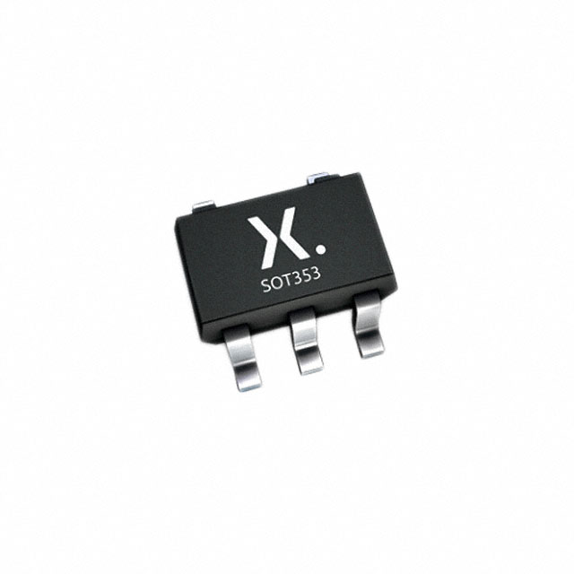
- Package: SOT753 (SC-70-5)
- Essence: Single gate buffer/driver
- Packaging/Quantity: Tape and Reel, 3000 pieces per reel
Specifications
- Supply Voltage Range: 2.0V to 5.5V
- Input Voltage Range: GND to VCC
- Output Voltage Range: GND to VCC
- Maximum Operating Frequency: 125 MHz
- Propagation Delay: 4.3 ns (typical)
- Output Current: ±8 mA
- Input Capacitance: 3 pF
- Power Dissipation: 200 mW
Detailed Pin Configuration
The 74HCT1G126GW,165 has a total of 5 pins: 1. Pin 1: Input (A) 2. Pin 2: Enable (E) 3. Pin 3: Ground (GND) 4. Pin 4: Output (Y) 5. Pin 5: Power Supply (VCC)
Functional Features
- Non-inverting buffer/driver with 3-state output
- High-speed operation suitable for various applications
- Low power consumption makes it ideal for portable devices
- 3-state output allows multiple devices to share a common bus
Advantages and Disadvantages
Advantages: - High-speed operation enables efficient data transfer - Low power consumption prolongs battery life in portable devices - Small package size saves board space - 3-state output facilitates bus sharing in complex systems
Disadvantages: - Limited output current may not be suitable for driving heavy loads - Narrow supply voltage range restricts compatibility with certain systems - Input capacitance may affect performance in high-frequency applications
Working Principles
The 74HCT1G126GW,165 is a single gate buffer/driver that amplifies and buffers digital signals. It operates by receiving an input signal (A) and an enable signal (E). When the enable signal is high, the input signal is amplified and passed to the output pin (Y). Conversely, when the enable signal is low, the output pin is in a high-impedance state, effectively disconnecting it from the input.
Detailed Application Field Plans
The 74HCT1G126GW,165 is commonly used in various digital systems where buffering or driving of signals is required. Some specific application areas include: - Microcontrollers and microprocessors - Communication systems - Data acquisition systems - Industrial automation - Automotive electronics
Detailed and Complete Alternative Models
Some alternative models that can be considered as replacements for the 74HCT1G126GW,165 are: - SN74LVC1G126DBVR - MC74VHC1G126DF1G - TC7SZ126AFK(TE85L,F)
These alternatives offer similar functionality and characteristics, allowing users to choose the most suitable option for their specific requirements.
Word count: 348 words
Listen Sie 10 häufige Fragen und Antworten im Zusammenhang mit der Anwendung von 74HCT1G126GW,165 in technischen Lösungen auf
Sure! Here are 10 common questions and answers related to the application of 74HCT1G126GW,165 in technical solutions:
Q1: What is the function of the 74HCT1G126GW,165? A1: The 74HCT1G126GW,165 is a single bus buffer gate with 3-state output. It is used to control the flow of data between different parts of a circuit.
Q2: What is the voltage range supported by the 74HCT1G126GW,165? A2: The 74HCT1G126GW,165 supports a voltage range of 4.5V to 5.5V.
Q3: How many inputs does the 74HCT1G126GW,165 have? A3: The 74HCT1G126GW,165 has one input.
Q4: How many outputs does the 74HCT1G126GW,165 have? A4: The 74HCT1G126GW,165 has one output.
Q5: Can the 74HCT1G126GW,165 be used for level shifting? A5: Yes, the 74HCT1G126GW,165 can be used for level shifting as it supports both TTL and CMOS logic levels.
Q6: What is the maximum operating frequency of the 74HCT1G126GW,165? A6: The maximum operating frequency of the 74HCT1G126GW,165 is typically around 125 MHz.
Q7: Does the 74HCT1G126GW,165 have internal pull-up or pull-down resistors? A7: No, the 74HCT1G126GW,165 does not have internal pull-up or pull-down resistors.
Q8: Can the 74HCT1G126GW,165 be used for bidirectional communication? A8: No, the 74HCT1G126GW,165 is a unidirectional buffer and cannot be used for bidirectional communication.
Q9: What is the power supply current required by the 74HCT1G126GW,165? A9: The power supply current required by the 74HCT1G126GW,165 is typically around 4 mA.
Q10: Is the 74HCT1G126GW,165 available in different package options? A10: Yes, the 74HCT1G126GW,165 is available in different package options such as SOT353 and XSON6.